WebIO 7
Automation
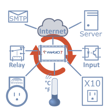
WebIO7 internal automation will monitor your sensors and use defined rules to control your devices and send notificaitions.
An automation rule lets you define a trigger that will cause an action. WebIO7 currently supports 6 user defined automation rules.
An automation trigger can be defined as a hardwired input state (high or low) or a wireless temperature value. An action can be defined as a Relay state, RF Outlet On/Off message, X10 powerline message, HTTP-GET message, or an SMTP Email.
The example automation rules below demonstrate a number of automation examples.
WebIO7 control automation
Wired Inputs controlling Relays Example
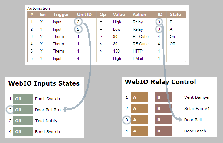
The WebIO7 automation table above is taken from the WebIO7 Automation webpage. The input state indicators and relay controls are take from WebIO7 Relays & Inputs webpage.
This example demonstrates automation rules for a wired input controlling a relay.
Rule #1 defines Input #2 (Unit 2) will set Relay #3 (ID 3) to state "B" (energize/on statem, Normaly open is now closed) when the Input transitions to a High state (input voltage is > 3.5 volts).
Rule #2 defines Input #2 (Unit 2) will set Relay #3 (ID 3) to state "A" (not energized/off state, normaly open is open) when the Input transitions to a Low state (input voltage is < 3.5 volts).
Note that the automation table does not display the input or relay user labels/names but instead referes to inputs and relays by number, as indicated by the overlayed blue circles.
Note that the "En" (Enabled) column displayes a "Y" for rule is enabled or "N" for rule is not enabled. A rule will only execute if it is defined to be Enabled. This feature allows you to disable a rule that you may want to enable again at a later time.
Temperature Controlling Wireless AC Outlets Example
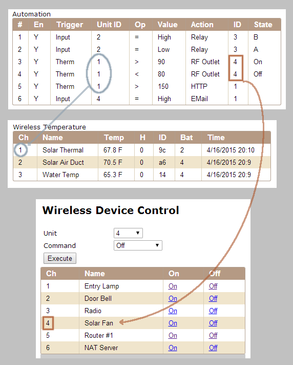
The WebIO7 automation table above is taken from the WebIO7 Automation webpage. The Wireless Temperature table it taken from the WebIO7 Temperature webpage and the Wireless Device Control table is take from the WebIO7 RF Control webpage.
This example demonstrates automation rules for a wireless temperature sensor controlling a wireless AC outlet. In this example the temperature sensor is located in solar thermal panel and the AC outlet turns on/off an electrical air duct fan.
Rule #3 defines temperature sensor #1 (Unit 1) will turn on wireless outlet #4 (ID 4) when the temperature is > 90 Fahrenheit.
Rule #4 defines temperature sensor #1 (Unit 1) will turn off wireless outlet #4 (ID 4) when the temperature is < 80 Fahrenheit.